Controlling the mold temperature is crucial when it comes to the optimization of a part using the injection molding processes. Software calculations can help find the best thermal design to improve the part quality.
Thermal mold design is one of the most critical parameters determining the performance of an injection molding operation. Up to now, a lot was left to guessing and prior experiences, but this approach is changing with the latest simulation tools. One of the pioneers has been IPC (Innovation Plasturgie Composites, from Oyonnax in France), who, for years, has successfully been using SIGMASOFT® Virtual Molding for designing the thermal layout of their injection molds.
IPC’s approach has been to virtually analyze the impact of different cooling concepts to find the one that suits their requirements best. The company combines traditional cooling systems with conformal cooling. The analysis performed with SIGMASOFT® Virtual Molding enables them to quickly detect the impact of every iteration in the mold performance (in terms of cycle time) and on the part quality (regarding warpage and residual stresses).

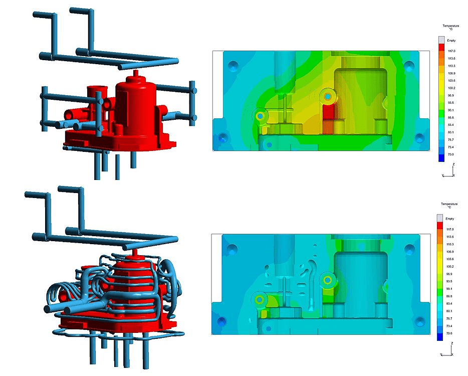
In Figure 1, the temperature in the mold is compared at the same cycle time for both tempering concepts. As seen, the temperature gradient in the mold is substantially reduced when using the conformal cooling configuration. The temperature in the cavity is almost homogeneous and the peak value of heat concentration is reduced from 117°C to 93°C. With this reduction in mold temperature, especially reducing the heat concentration at critical areas, the cycle time has been reduced by almost 27%.
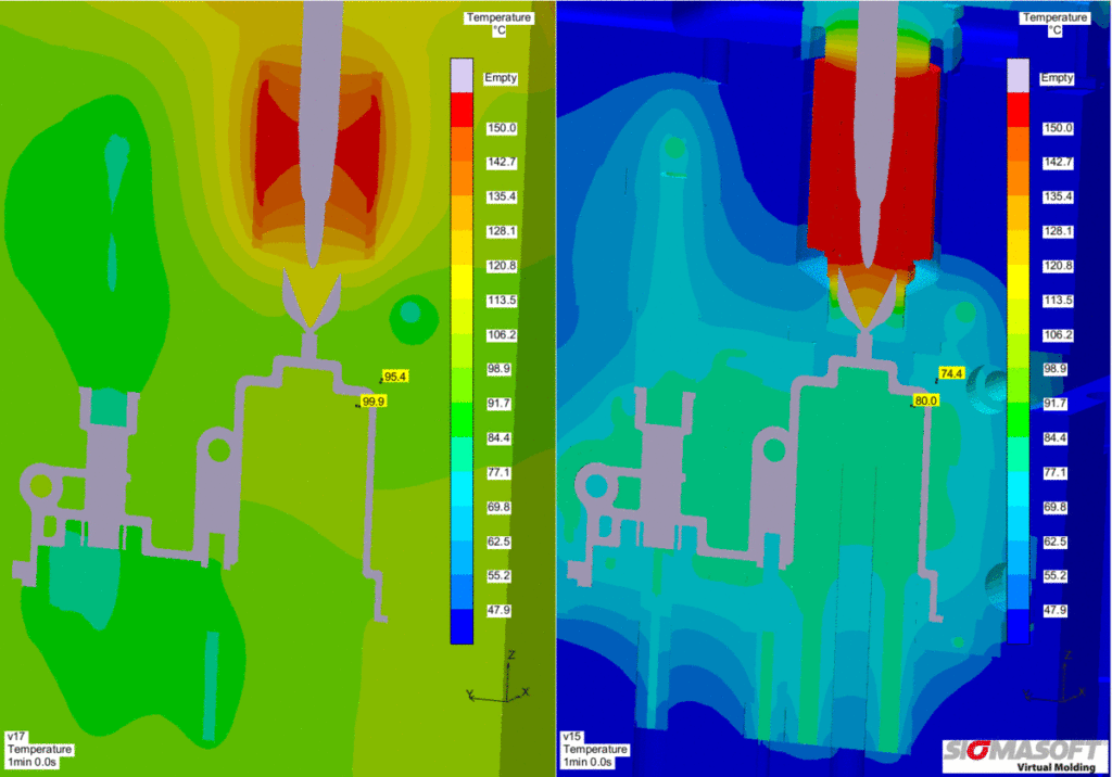
Additionally, the overall heat transfer distribution in both mold halves has been improved utilizing the conformal cooling configuration. On the left side of Figure 2, the behavior of the mold temperature during a molding cycle is presented for the original cooling configuration. The right side shows the same molding cycle using the conformal cooling configuration. It is evident that the conformal cooling can maintain the temperature in the mold cavity closer to the objective value (80°C).
Furthermore, Figure 2 points out that the influence zone of the hot runner system has been confined. Limiting this influence zone improves part quality and reduces cycle time.

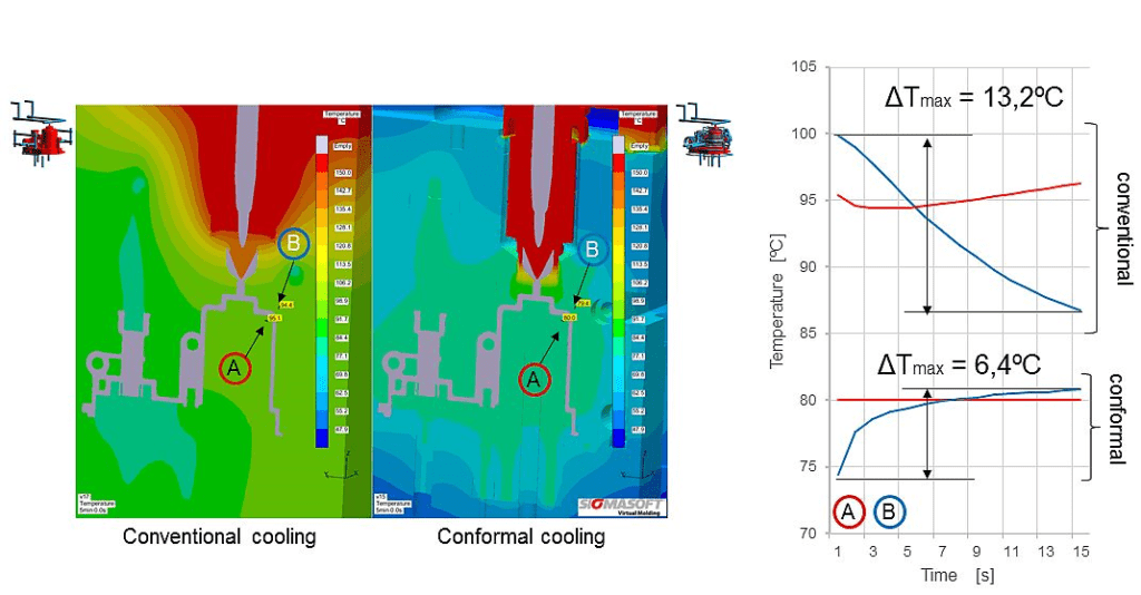
An additional benefit of conformal cooling was quantified by placing two sensors, one on the movable half and one on the fixed half. The objective was to account for the difference between both mold halves, knowing that temperature gradients will have a negative impact on part deformation.
As seen in Figure 3, the maximum temperature gradient was reduced from 13,2°C to 6,4°C between both mold halves over the molding cycle. As an additional benefit, the temperature of the fixed half on the conformal cooling configuration was set to remain almost unchanged during the cycle fraction observed, proving once more the benefit of isolating the heat coming from the hot runner system.