The selection of the ejection system is typically an intuitive process while designing an injection mold. Usually, the designer determines the best location for the ejection pins based on previous experiences. However, sometimes the performance of the ejection system deviates from the designer’s expectation. In the worst case, the contraction of the part towards the mold cores impairs a correct ejection, or the designed system does not work properly.
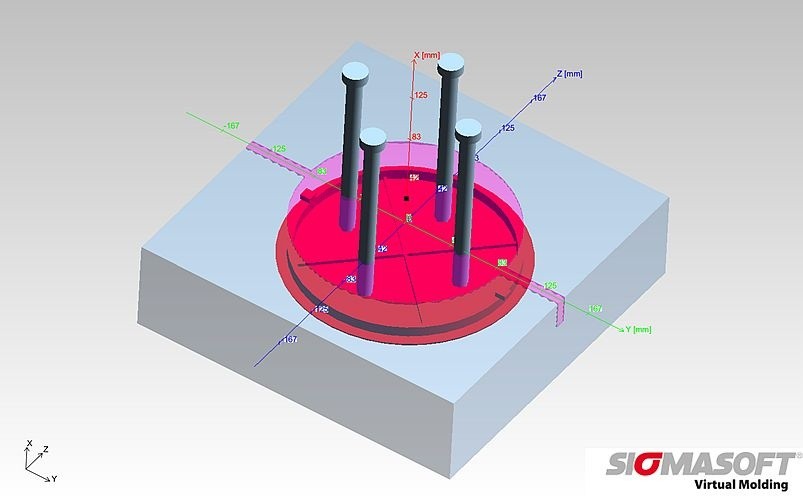
The molder of a cosmetic packaging wanted to design the ejection system for a round cover, molded in PP. This part should be released without any visible marks, as the aesthetic requirements for this kind of packaging are very high. Initially, the ejection concept shown in Figure 1 was proposed.
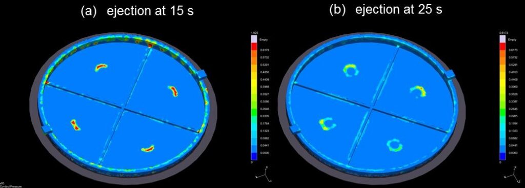
The SIGMASOFT® Virtual Molding simulation showed that the part achieved complete solidification at 12s, the ejection was simulated at 15s accordingly. However, the results showed that the part was shrinking away from the pins, as shown in Figure 2a. The part was “sticking” to the core, and only one side of the pins was acting on the part, as seen in Figure 3a.
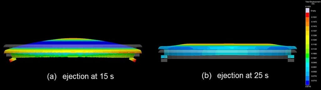
Another simulation was run, with an ejection after 25 seconds. The part deformation was observed to be substantially smaller, as seen in Figure 2b, so that the whole surface of the pins fulfilled their task. The ejection contact pressure for this longer cycle time was lowered by almost 70%, as can be seen in Figure 3b.
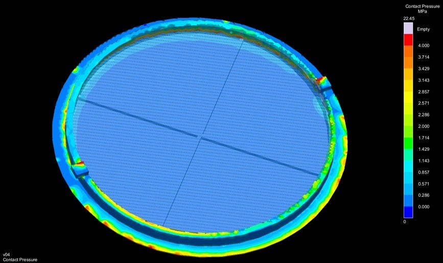
To achieve the desired ejection performance and to have lower contact pressure, the cycle time for this ejection configuration needed to be longer. When attempting to cut out cycle time, the contact pressure of the pins increased, risking marks in the part’s surface. Therefore, a second configuration was proposed, as seen in Figure 4. With the help of the ejector ring marks on the part surface should be avoided.
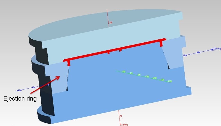
Again, the ejection was simulated at 15s. The part warped again in the center, following the shape seen in Figure 2a, but the ejection ensued over the perimeter of the part. The contact pressure during ejection for the new configuration is displayed in Figure 5. Finally, this configuration was selected, as it allowed applying ejection pressure effectively to where the part was “sticking”, it left no marks on critical surface areas and allowed a shorter cycle time. The part design was ultimately modified to avoid undercuts and to enable ejection in this configuration.