Effect of the Hot Runner on the Mold Cooling

Download

Effect of the Hot Runner on the Mold Cooling

Published in the magazine: Kunststoffe International 12/2012, page 50-52

Authors: Marco Thornagel and Vanessa Schwittay

Injection Molding Simulation. Although hot-runner systems have a considerable influence on the  productivity of injection molding processes, they are often neglected in injection molding simulation. How can the  simulation only focus on the plastic article and not consider factors of influence on article quality, process stability and value creation?

 (c) Günther Heißkanal

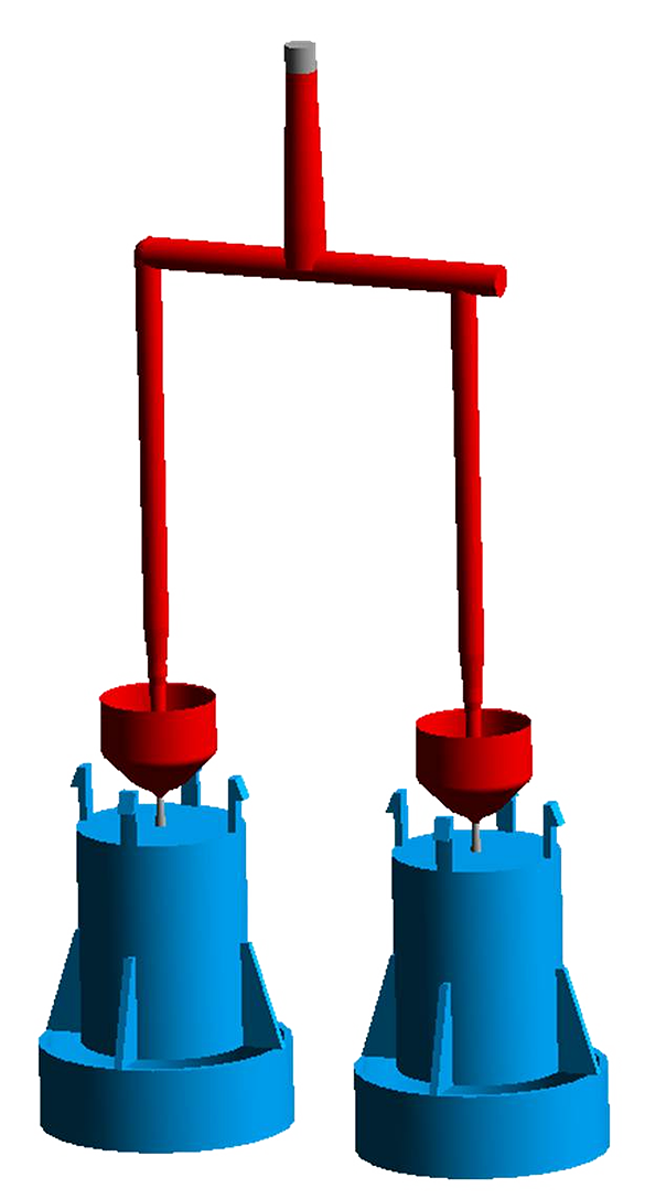
The simulation should ideally take into account the complete hot runner with all its geometries and materials. Intermediate solutions are a help, though (figure: Günther)

In injection molding simulation, a realistic computation of the temperature distribution in hot-runner molds means taking into account not only the mold components, but also the geometries and materials of the hot runner. After all, it is only with a correct simulation of the thermal state of the cavity and the entire mold that a realistic rheological analysis of the injection molding process can be made and detailed information provided about the thermal relationships in the mold. However, the complete hot-runner geometries are only rarely available. The hot runner is therefore usually completely neglected in the simulation and at best replaced by an idealized runner. However, this major oversimplification has an effect not only on the thermal situation in the mold, but also reduces the value of the prediction of quality and properties of the part.

No Reliable Prediction

Complete neglect of the hot-runner system would only be permissible on the assumption that the hot runner has no significant effect on the mold thermal balance and does not heat up the mold at any point, or otherwise influence it. Apart from that, the user would also have to assume that neither pressure losses nor shear heating take place in the melt channel, so that these effects are not relevant for the simulation.

But every practitioner knows that this is not the case and the hot runner, its components and controller significantly influence the actual process and the article properties. Simulations that do not precisely take into account the hot-runner system therefore cannot provide realistic results for filling pattern, pressure demand and temperature distribution – significant differences between the simulation and reality occur, in particular regarding the holding pressure effect, clamping force, cooling time, shrinkage and warpage. On this basis, it is impossible to make a reliable prediction of the process and part quality.

Hot-runner manufacturers – for understandable reasons – do not make their precise system set-up available in detail as a CAD record. But what possibilities are there for improving the results of the injection molding simulation without a detailed knowledge of the hot-runner geometry? But, between the two extremes of completely taking into account all components and materials, on the one hand, and the vast oversimplification of an idealized runner on the other hand, various intermediate solutions are feasible. Thus, an improved computation of the pressure demand is already possible with a fast 3-D flow simulation of the adiabatic melt channel. The heat that is input by the hot-runner system, and its influence, e.g., on the warpage of the plastic article, can already be represented using the data on the hot-runner system that are available as standard, and a Sigmasoft Multi-Cycle Analysis (software supplier: Sigma Engineering GmbH, Aachen, Germany), as is shown below.

The Question of the Pressure Loss

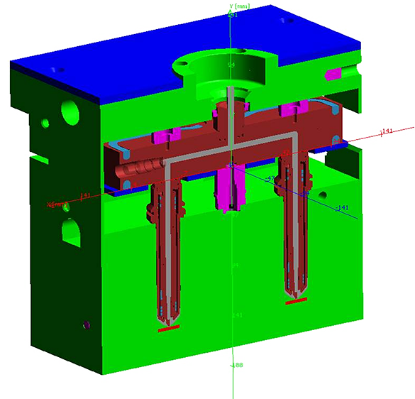
A particular application often requires a fast and accurate prediction of the pressure demand, for example to allow the possible number of cavities or the size of the injection molding machine to be determined. While the pressure loss of the cavities is usually known from previous injection molding simulations, the question of the total pressure loss arises, which depends on the chosen hot-runner system. The hot-runner manufacturer usually makes the actual melt runner, comprising manifold and nozzles, available as a CAD record (Fig.1). Considering this melt channel as adiabatic in the simulation, i.e. virtually isolating it with respect to the mold, is a quick and simple way of improving the predictive power of the simulation.

 

 (c) SIGMA Engineering GmbH

Fig. 1. To represent the influences of pressure loss, shearing heating and an imbalance in the runner due induced by shearing, only the geometry of the melt channel, which is assumed to be adiabatic, must be considered (figure: Sigma)

In the simulation of an adiabatic melt channel, therefore, only its geometry in the interior of the hot-runner system is taken into account, while its exterior geometry and all material properties are neglected. The pressure loss occurring in the melt channel and the resulting shear heating are just as completely reproduced by the simulation as the unbalanced melt flow caused by shearing. An additional increase of the imbalance of this system can now only occur as a result of the temperature control of the nozzles. The same relationship appears in principle for the melt viscosity and its influence on the pressure loss.

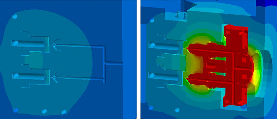
The use of an adiabatic hot runner in the simulation provides more realistic times for the cooling and holding-pressure phases and a more accurate holding pressure effect. The simulated warpage of the part, too, is closer to the real value than if the hot runner is neglected and replaced by a simple runner. However, in this form, the hot runner has no influence on the thermal situation in the mold (Fig.2, left), since the adiabatic system does not emit heat to the mold.

 (c) SIGMA Engineering GmbH

Fig. 2. Taking into account the hot-runner, represented simplified as a heat source (right), has a significant influence on the mold temperature control; this is not the case with an adiabatic hot runner (left) (figure: Sigma)

The Hot-Runner Block as Heat Source

For many applications, it is worth going a step further and representing the effect of the hot-runner even more accurately. The hot-runner manufacturer specifies the cut-out in the mold, i.e. the space that must be allowed for the hot runner. The manufacturer also supplies the outer shape of the hot-runner geometry in order to check the installation situation. If this information is expertly used, the simulation of the heat input from the hot runner into the mold via the contact surfaces can be represented with adequate precision. Thus, the prediction quality of the simulation is significantly improved overall.

In this simulation, the entire hot runner block serves as a heat source with a homogeneous temperature. Since the contact surfaces between the mold and hot-runner system are known, the influence of the hot runner on the temperature distribution in the mold becomes visible in a multi-cycle simulation (Fig.2, right). With this form of hot-runner simulation, not only are the pressure loss, shear heating and imbalance due to the melt channel represented, but also the heating of the mold by the hot runner (hotspot) is reproduced. Compared to the standard simulation, the warpage of the article changes significantly (Fig.3), the result is thus much closer to reality.


 (c) SIGMA Engineering GmbH

Fig. 3. If the heating of the mold is taken into account (right), the warpage of the part is much greater compared to a standard simulation (left) and agrees better with the real situation (figure: Sigma)

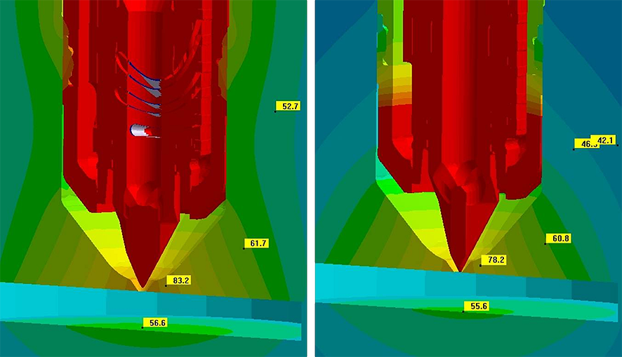
The question remains as to how far it is justified to assume that the hot runner is a homogeneous heat source. For this purpose, Sigma Engineering, together with Günther Heisskanaltechnik GmbH, Frankenberger, Germany, has analyzed and completely simulated hot-runner systems (Fig.4). If we compare the two results, we can see very similar temperatures in the important vicinity of the cavity. In regions remote from the cavity, the mold becomes significantly hotter with simplified hot-runner modeling, since the spatial configuration of the insulating material around the hot runner and its properties do not enter into the simulation. The above-described procedure for better integration of hot-runner systems into the simulation is therefore justified and provides a more accurate description of the article properties (in this case warpage) and the thermal situation close to the cavities in the mold.

 (c) Günther Heißkanal

Fig. 4. Comparison of the temperature distribution in the mold with a simplified view of the hot-runner block as heat source (left) and in the case of a completely simulated hot runner system with all components (right). The temperature distribution in the important region of the cavity is similar in both variants. Remote from the cavity, the simplified geometry heats up the mold because of the lack of insulation (figure: Günther)

Summary

Between the more detailed consideration of all hot-runner geometries and the complete neglect of the hot runner, there are thus various ways of better taking into account real influences in the simulation. The more information is provided about the hot runner, the more realistic are the simulation results. Including more details does not mean that the effort for simulation preparation or the computation time is necessarily greater. Sigmasoft allows engineers to set up and simulate even extensive models within a short time. Why, therefore, should we continue to accept oversimplified models?